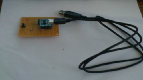
UARTサンプル
#include <stdio.h>
#include <htc.h>
#include "usart.h"

 __CONFIG(MCLRE_OFF & PWRTE_ON & WDTE_OFF & FOSC_INTOSCIO & LVP_OFF);

void main(void){
	unsigned char input;

	INTCON=0;	// purpose of disabling the interrupts.

	init_comms();	// set up the USART - settings defined in usart.h

	// Output a message to prompt the user for a keypress
	printf("\rPress a key and I will echo it back:\n");
	while(1){
		input = getch();	// read a response from the user
		printf("\rI detected [%c]",input);	// echo it back
	}
}
usart.h
#ifndef _SERIAL_H_
#define _SERIAL_H_

#define BAUD 9600
#define FOSC 4000000L
#define NINE 0     /* Use 9bit communication? FALSE=8bit */

#define DIVIDER ((int)(FOSC/(16UL * BAUD) -1))
#define HIGH_SPEED 1

#if NINE == 1
#define NINE_BITS 0x40
#else
#define NINE_BITS 0
#endif

#if HIGH_SPEED == 1
#define SPEED 0x4
#else
#define SPEED 0
#endif

//#if defined(_16F87) || defined(_16F88)
//	#define RX_PIN TRISB2
//	#define TX_PIN TRISB5
//#else
//	#define RX_PIN TRISC7
//	#define TX_PIN TRISC6
//#endif
	#define RX_PIN TRISB1
	#define TX_PIN TRISB2


/* Serial initialization */
#define init_comms()\
	RX_PIN = 1;	\
	TX_PIN = 1;		  \
	SPBRG = DIVIDER;     	\
	RCSTA = (NINE_BITS|0x90);	\
	TXSTA = (SPEED|NINE_BITS|0x20)

void putch(unsigned char);
unsigned char getch(void);
unsigned char getche(void);

#endif
#include <htc.h>
#include <stdio.h>
#include "usart.h"

void
putch(unsigned char byte)
{
	/* output one byte */
	while(!TXIF)	/* set when register is empty */
		continue;
	TXREG = byte;
}

unsigned char
getch() {
	/* retrieve one byte */
	while(!RCIF)	/* set when register is not empty */
		continue;
	return RCREG;
}

unsigned char
getche(void)
{
	unsigned char c;
	putch(c = getch());
	return c;
}
PIC16F648A
PIC16F84Aの置き換えに最適
特徴
内蔵OSC(4 MHz)
リセット回路内蔵
コンフィグレーションワードで指定するところが味噌です。
リセット回路については、
・MCLRE=0 RA5/MCLRピンをディジタルI/Oとして使う
・PWRTE=1 パワーアップ タイマを使う
・BOREN=1 電源電圧低下時にリセットを発生させる。状況によりますが有効にしておいた方が安全でしょう。
発振器については
・FOSC<2:0>=100 内蔵発振器を使う。RA6/OSC2とRA7/OSC1ピンはディジタルI/Oとして使う
となるようにコンフィグレーションワードの設定をします。
http://www6.ocn.ne.jp/~sunnydog/theme03/theme03.htm
上記の設定で電源、GNDを与えるだけで16PIN I/Oが使用可能
但し
RA4/T0CKIピンは出力がオープンドレイン、RA5/MCLRピンは入力のみ
HI-TECH Cでのコンフィグはこんな感じで
__CONFIG(MCLRE_OFF & PWRTE_ON & WDTE_OFF & FOSC_INTOSCIO & LVP_OFF);
スイッチ一つでCtrl+Alt+Delをやってみた
C:\Microchip Solutions v2012-08-22\USB\Device - HID - Keyboard\Keyboard.c の中身をこんな風に変更
void Keyboard(void)
{
	static unsigned char key = 0x4c;//DEL

	//Check if the IN endpoint is not busy, and if it isn't check if we want to send
	//keystroke data to the host.
    if(!HIDTxHandleBusy(lastINTransmission))
    {
        if(Switch3IsPressed())
        {
        	//Load the HID buffer
        	hid_report_in[0] = 0b00000101;//左ALT+左Ctrl
        	hid_report_in[1] = 0;
        	hid_report_in[2] = key;
        	hid_report_in[3] = 0;
        	hid_report_in[4] = 0;
        	hid_report_in[5] = 0;
        	hid_report_in[6] = 0;
        	hid_report_in[7] = 0;
           	//Send the 8 byte packet over USB to the host.
           	lastINTransmission = HIDTxPacket(HID_EP, (BYTE*)hid_report_in, 0x08);

//            if(key == 40)
//            {
//                key = 4;
//            }
        }
        else
ミニミニキーボードの作成

スイッチを押すとエンターキーをPCに送るミニミニキーボードを作成しました。
C:\Microchip Solutions v2012-08-22\USB\Device - HID - Keyboard\Keyboard.c の中身をこんな風に変更
void Keyboard(void)
{
	static unsigned char key = 40;	//Enter

	//Check if the IN endpoint is not busy, and if it isn't check if we want to send
	//keystroke data to the host.
    if(!HIDTxHandleBusy(lastINTransmission))
    {
        if(Switch3IsPressed())
        {
        	//Load the HID buffer
        	hid_report_in[0] = 0;
        	hid_report_in[1] = 0;
        	hid_report_in[2] = 40;	//Enter
        	hid_report_in[3] = 0;
        	hid_report_in[4] = 0;
        	hid_report_in[5] = 0;
        	hid_report_in[6] = 0;
        	hid_report_in[7] = 0;
           	//Send the 8 byte packet over USB to the host.
           	lastINTransmission = HIDTxPacket(HID_EP, (BYTE*)hid_report_in, 0x08);
EnterのUSB キーコード
こちらのテーブルからEnterは40(=0x28)だとわかった。
http://hamayan.blog.so-net.ne.jp/archive/c40385105-1
PIC18F14K50
PIC18F14K50使用USB対応超小型マイコンボード説明書
http://akizukidenshi.com/download/ds/akizuki/AE-PIC18F14K50.pdf
PIC18F14K50データシート(日本語)
http://ww1.microchip.com/downloads/jp/DeviceDoc/41350D_JP.pdf
このキットでもUSB Bootloaderと仮想COMのサンプルソフトがそのまま動いた。
PIK KIT3で書込
仮想COMは
C:\Microchip Solutions v2012-08-22\USB\Device - CDC - Basic Demo\Firmware
の「USB Device - CDC - Serial Emulator - C18 - Low Pin Count USB Development Kit.mcp」をダブルクリックしてを書き込む
キット単体だとVPPをプルアップしないとリセットがかかるので注意